So, you’ve finally done it. You upgraded your sim racing setup. You’ve got a high-end direct-drive wheelbase bolted to the rig, a set of professional load-cell pedals underneath you, and life is good.
But then you look in the corner of your room and see your old gear sitting there. In my case, I had a perfectly functional Logitech H-pattern shifter and a set of pedals. The catch? They use proprietary DB9 connectors meant to plug directly into a Logitech wheel base. If you move to an independent ecosystem like Simagic, those peripherals instantly become useless paperweights—unless you buy an overpriced proprietary adapter, or you have an Arduino Pro Micro, a soldering iron, and a bit of developer stubbornness.
I chose the latter.
Instead of throwing money at a simple hardware conversion, I decided to build a standalone, plug-and-play USB HID interface. Here is the story of how I took raw analog joystick data, ran it through an Arduino, fought electrical noise, and emerged with a rock-solid H-pattern shifter that runs beautifully alongside premium direct-drive hardware.
The Core Concept & Bill of Materials
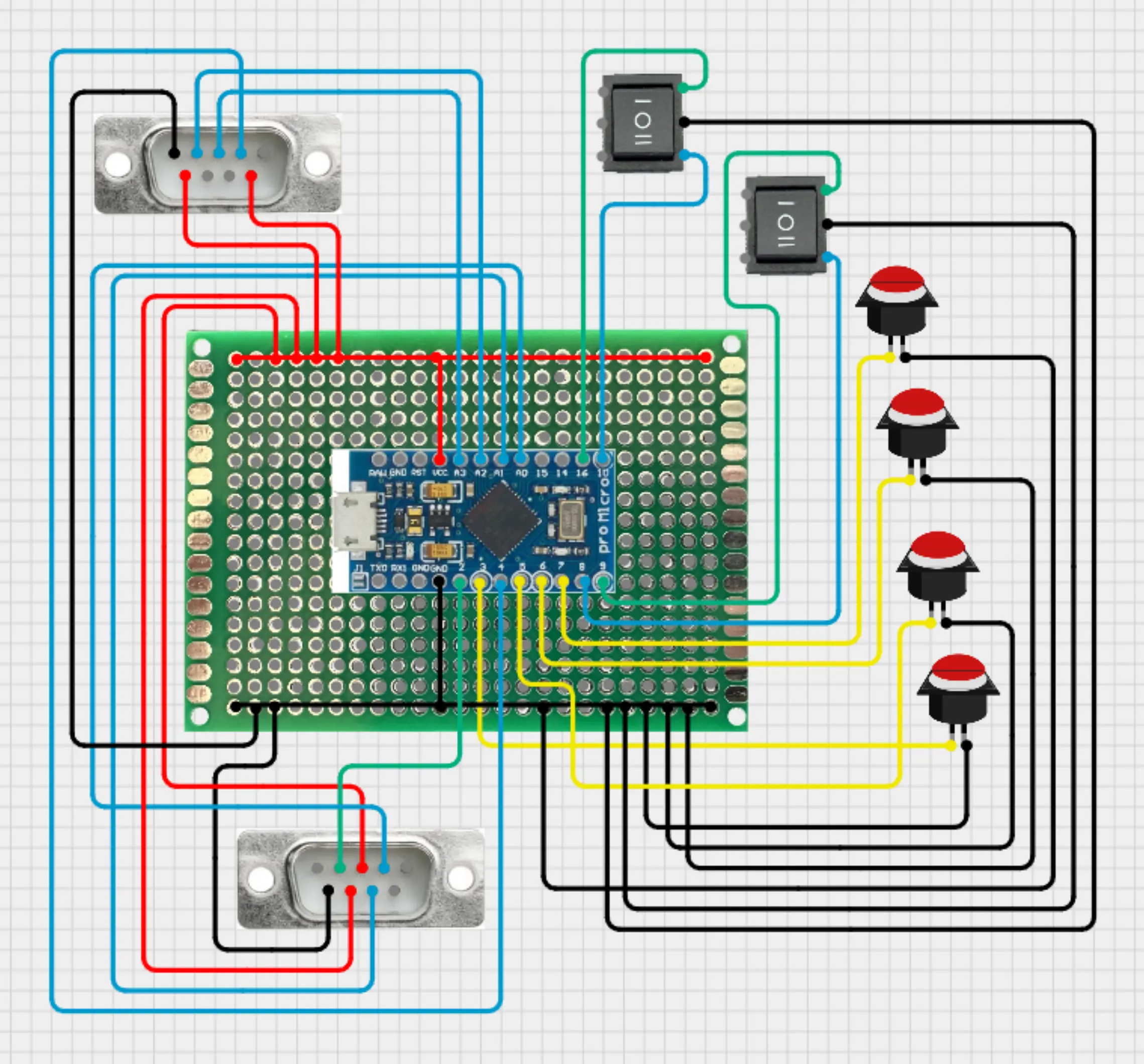 The goal was straightforward: create a standalone USB device that Windows recognizes natively as a gamepad. No external drivers, no background emulation software running in the taskbar. To bridge the gap between physical traces and USB packets, I used an Arduino Pro Micro. Unlike a standard Uno or Nano, the Pro Micro uses the ATmega32U4 chip, which has built-in USB communication capabilities. This allows it to masquerade flawlessly as a Human Interface Device (HID)—a native joystick.
The Materials:
-
Brain: Arduino Pro Micro (ATmega32U4).
-
Inputs: Legacy H-pattern shifter (utilizing an internal 2D analog potentiometer joystick and a microswitch for reverse) + 3 analog pedal potentiometers.
-
Miscellaneous: Jumpers, a prototype board, and a micro-USB cable.
For the wiring schematics and interactive circuit layout, I mapped everything out on my Cirkit Designer Project Page. But while the wiring is relatively basic pins-to-pots electronics, making the software behave like a premium automotive component was where the real fun began.
Phase 1: The Compilation Trap (15 vs 16 Arguments)
I started the project using Matthew Heironimus’s excellent Arduino Joystick Library. I wanted to map the raw X and Y axes of the shifter, three pedal axes, a reverse button, and a few miscellaneous toggle switches.
I wrote out what I thought was a flawless configuration constructor, hit upload, and was immediately smacked with a brutal compiler error:
Compilation error: no matching function for call to 'Joystick_::Joystick_(...)'
As it turns out, I fell straight into a classic library versioning trap. I had supplied 16 arguments to the constructor initialization block, but the library only expects exactly 15. I had explicitly declared a dedicated boolean flag for a clutch axis at the very end of the array. In this library, specialized racing axes like the clutch don't get their own initialization boolean; they are handled under the hood by generic rotational axes (like Ry).
Dropping the 16th argument or reverting to the library's default clean Joystick_ SimRig; constructor bypassed the strict argument counting entirely and got the code compiling instantly.
Phase 2: Translating a Crosshair into Gear Gates
When you plug a Logitech shifter into an analog reader, Windows doesn't see "Gear 1" or "Gear 6." It sees a 2D crosshair moving smoothly on an X and Y plane, exactly like a thumbstick on a gamepad.
Furthermore, because of how consumer potentiometers are manufactured, the pedals and shifter never sweep perfectly from absolute 0 to absolute 1023. They have built-in physical deadzones (operating roughly from 10% to 90% of total electrical rotation). Fortunately, modern simulators like Assetto Corsa Evo or iRacing handle this axis scaling automatically via their in-game calibration wizards.
The real challenge was writing software logic to parse the X/Y grid and tap virtual Windows buttons when the stick entered a specific "gate."
       [Y-Axis High: Odd Gears]
          Gear 1   Gear 3   Gear 5
            |        |        |
[X Low] ----+--------+--------+---- [X High]
(Left Gate) |     (Center)    |  (Right Gate)
            |        |        |
          Gear 2   Gear 4   Gear 6
          [Y-Axis Low: Even Gears]
By using strict coordinate thresholds, I mapped out a grid:
- Left Gate (X < 270): Pushed up for 1st gear, pulled down for 2nd gear.
- Right Gate (X > 560): Pushed up for 5th gear, pulled down for 6th gear.
- Center Gate (Default): Pushed up for 3rd gear, pulled down for 4th gear.
Phase 3: Taming the Analog Noise (The "Blinking" Problem)
Once the coordinate mapping was flashed, I opened Windows Game Controller settings (joy.cpl) to test it. When I pushed the stick into gear, the corresponding red button indicator lit up. Success!
...Except it didn't stay lit. It rapidly vibrated, blinked, and flickered.
This is a classic hardware reality: electrical noise. Mechanical gear shifters naturally have play in them, and cheap analog potentiometers constantly experience micro-voltage drops. Because the Arduino loops thousands of times per second, if your shifter rests even slightly close to a threshold boundary (e.g., an X value fluctuating between 269 and 271), the code triggers a chaotic storm of gear-to-neutral-to-gear state changes.
To fix this, I implemented a temporal software debounce.
Instead of letting the Arduino immediately signal a gear change to Windows, I forced it to wait. The code now continuously samples the gear zone. The stick must sit firmly, completely still, inside a specific gate for at least 50ms before the Arduino registers the change. If an electrical spike drops back to neutral for even a single millisecond during that window, the timer resets.
The result? Rock-solid, non-flickering button responses in Windows.
Phase 4: The Reverse Gear Paradox
Just when I thought the project was finished, I found one last quirk. When slamming the shifter into the Reverse pocket, joy.cpl showed that both Button 1 (Reverse) and Button 15 (6th Gear) were lighting up simultaneously.
Mechanically, this makes total sense. To enter reverse on a Logitech shifter, you push down and slam the stick into the bottom-right corner—the exact same physical neighborhood where 6th gear lives. The analog pots were reading the 6th gear coordinates, while the physical microswitch at the bottom of the well was getting clicked for Reverse.
Leaving this as-is would completely break a racing sim's input logic. I resolved this by enforcing an absolute software priority in the H-pattern state machine:
if (digitalRead(PIN_REV) == HIGH) {
// Force all analog forward gears
// to Neutral
  currentGear = 0;
} else {
  // Standard X/Y coordinate checks
}
Now, the moment the reverse microswitch goes active, the Arduino completely blinds itself to the analog joystick positions, instantly cutting off the 6th gear signal and passing only the Reverse button output to the PC.
The Finish Line
There is an immense level of satisfaction that comes from clicking a DIY shifter into place. By stripping out debugging serial prints and optimizing the code, the Arduino handles the entire state machine with practically zero input latency.
I now have a robust, completely independent shifting and pedal setup running alongside a world-class direct-drive wheelbase. Total cost? A few dollars for an Arduino and an afternoon spent coding and troubleshooting.
If you want to build this exact interface for your own rig, you can find the complete, production-ready code on my GitHub repo.
See you on the track ;)